CONTROL Parameters
Offset Round⁄Tapered Walls: See description of M95 and M96 (pages 7-6 to 7-10).
Chip Remove On (Min): If the machine is equipped with a chip removal system, this
specifies the time that the auger will run after an M38 or after pushing the front panel Auger button.
Wash Down On ⁄ Off (Sec): The wash down cycles on and off using these times.
Auto Rotary Brake: “Yes” will control the rotary brake on A and B axis automatically.
The brake is released before rotary moves, and it is clamped when the move is complete.
“No” requires M10⁄11 and M12⁄13 to turn the brake off⁄on.
Rotary Brake Delay (Secs): This is the delay in seconds after an M11 (A axis brake release)
and M13 (B axis brake release). It is also the delay time after autobrake release in Home, Jog,
and Handwheel. The default is .25 seconds. Max is 2.55 seconds.
Check 4 th Axis Unclamp Switch Yes if the 4 th axis has an unclamped switch.
Check 4 th Axis Clamp Switch Yes if the 4 th axis has an unclamped switch.
Check 5 th Axis Unclamp Switch Yes if the 5 th axis has an unclamped switch.
Check 5 th Axis Clamp Switch Yes if the 5 th axis has an unclamped switch.
Ignore Tool too Large Errors: If set, the errors: #507 After compensation line to arc lacks
intersection. #569 The tool is too large to cut inside the arc “Compensated radius is to small”
#579 Compensated arcs do not intersect. Are ignored and compensation is done on a line from
the start of the arc to the end of the arc.
Enable Modify Column Displays Enables the function keys to change the axis positions under
F6 (Display). Options are: Current, Target, Distance, Machine, Measure, Actual, None or Error.
Pre Check Software Limits
Never:
the control never checks the soft limits. The soft limit error only occurs when the axis moves
outside the limits.
Run Only:
checks are not made when verifying. When running, the control will check to see if any axis
is going to move outside the limits before the move starts. The graphics will show the move
but the machine will not make the move. This can prevent crashes where faster moves go
beyond the limits.
Always:
the control will check to see if any axis is going to move outside the limits when running or
verifying. The graphics will show the move, but the machine will not make the move.
It may be useful to verify a program before running it.
Tool Load Flag Limit Exceeded or Limit not exceeded
Tool Load Monitor - There are currently six options:
Off: No tool⁄spindle monitoring will be done.
E-Stop: If the limit is exceeded the machine will E-stop and display a message.
Feed Hold: If the Limit is exceeded the machine will Feed Hold and display a message.
Block Mode On: If the Limit is exceeded the machine will go into Block Mode and
display a message.
Set Flag-No Message: If the Limit is exceeded, the machine will set a flag. No message
is displayed. The flag is PB418. The program can check this parameter to see if the Limit
was exceeded and perform an alternate operation, change to a different tool, etc.
The operator can also view the state (or change the state) of the flag in the CTRL parameters.
The parameter “Tool Load Flag” has two states: Limit Exceeded or Limit not Exceeded.
Message Only: If the Limit is exceeded only the message is displayed.
Sampling is only done when the spindle drive is outputting up to speed, a program is running
and the spindle is on. The spindle load needs to stabilize after any change in RPM.
This requires that the software wait approximately 5 seconds after up to speed or any change
in the spindle override. The time is hard-coded (no parameter). The time is based on an
8,000 RPM two-speed spindle configuration. Different drives, spindles and⁄or drive parameters
may affect this delay time.
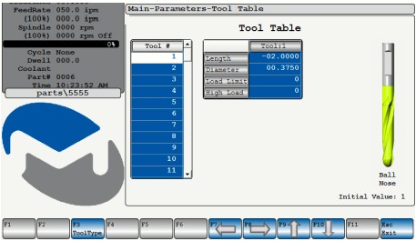
In the screen shot at the right below, the Load Limit and the High Load for each tool are shown below in the tool table (these fields were chosen in the “power” parameters). |
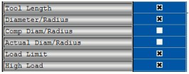 |
If a Limit for a tool is zero then no tool⁄spindle monitoring will be done. The High values are not
zeroed unless the operator zeros the values in the tool table. Initially the operator will run a program
and then observe the High values for each tool. For the tools that he wishes to monitor he loads
appropriate limits based on the High values that were obtained from running the program.