Detaillierte Maschinenparameter - Beschreibung
Machine Setup POWER Parameters
Initial Units are: G20 Inch or G21 Metric to power up in inch or metric.
Number of Axes: Can be 1 to 5.
Power-On Feedrate: Can be any number up to the maximum feedrate.
Spindle Axis: 1 to 5 1=X, 2=Y, 3=Z, 4=A, etc. Normally set to 3 for Z axis.
Primary HDW Encoder Axis:
The encoder to use for the primary handwheel. 8 for CNC8000 systems.
2nd Handwheel: Used for optional dual handwheel systems
(4 if it Encoder Axis: has the option).
3rd Handwheel: Used for optional dual handwheel systems
(5 if it Encoder Axis: has the option).
Remote HDW FOV1 thru FOV4: Sets the feedrate for the four feedrate switch
positions on the remote handwheel.
Remote HDW Encoder: The encoder to use for the remote handwheel.
Block Skip On: If Yes block skip is on at power up.
Optional Stop On: If Yes optional stop is on at power up.
Safe Zone On: If Yes safe zone is on at power up.
G22 turns the safe zone off.
G23 turns the safe zone on.
Manual Crank: Set to yes for machines that can be used as manual machines.
Allows X and Y axes to be moved using manual cranks.
Foreign Extension: Refers to the extension for data files. Current valid extensions
are listed below.
NOTE: Shift - F8 will toggle between English and any other language.
CHN CHINESE
ENG ENGLISH
SPN SPANISH
GRM GERMAN
Tool Table by: Radius or Diameter
***** Tool Table Fields *****
The following tool characteristics may be displayed in the tool table.
Diameter⁄Radius type
1. Compensation and Actual sizes. (selects both) For programs that have been compensated
for by CAD⁄CAM systems.The Compensation size is the difference between the CAD⁄CAM
comp size and actual size. The actual size is the physical tool size
-or-
2. Standard. The compensation size and the physical size are the same.
Tool Length: Yes⁄No
Diam⁄Radi Wear: Yes⁄No
Length Wear: Yes⁄No
Load Limit: (used for tool load monitoring) Yes⁄No
High Load: (used for tool load monitoring) Yes⁄No
Max RPM: Yes⁄No
Tool Type: Yes⁄No
****Tool Changer Information****
ATC Type is: Milltronics or Manual
Carousel Side Index Button: Yes for machines with tool loading station
Milltronics ATC is: Plunger, Geneva Two Step, Geneva One Step, Swing Arm,
or HM20 Swing Arm.
ATC tool (pocket count): Number of ATC pockets.
M6 (Tool Change) Macro: Name of the program used for custom M6, for example
“FAST.ATC”
Pot down on swing arm tool: Yes means the pot will be down for the pending
changers: tool. No means it will be up.
Dual-Acting Pot Down On Switch: For ATC’s that have outputs for potup and potdown
Check drawbar unclamped switch: Yes for machines with a proximity switch to detect the
drawbar unclamped.
Check drawbar clamped switch: Yes for machines with a proximity switch to detect the
drawbar clamped.
Drawbar Delay: Generally zero.
The parameter is retained for legacy carousel-style toolchangers as a delay (in seconds)
after the drawbar comes on and before the head goes up.
Arm Style Tool Spacing: The largest diameter tool (in inches) that can be loaded in a
tool carousel without interfering with the neighboring tool. Generally 3.00 Inch ⁄ 75 mm
Custom G⁄M Code Tables
Custom Gcode 09010 Custom Gcode 09011 Custom Gcode 09012 Custom Gcode 09013 Custom Gcode 09014 Custom Gcode 09015 Custom Gcode 09016 Custom Gcode 09017 Custom Gcode 09018 Custom Gcode 09019 |
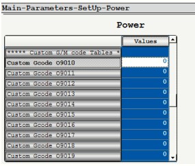 |
| Custom Mcode 09020 Custom Mcode 09021 Custom Mcode 09022 Custom Mcode 09023 Custom Mcode 09024 Custom Mcode 09025 Custom Mcode 09026 Custom Mcode 09027 Custom Mcode 09028 Custom Mcode 09029 Custom Mcode 09030 Custom Mcode 09031 Custom Mcode 09032 Custom Mcode 09033 Custom Mcode 09034 Custom Mcode 09035 Custom Mcode 09036 Custom Mcode 09037 Custom Mcode 09038 Custom Mcode 09039 |
When the G or M code is executed the 090## program (in the ram folder) associated will be called. All custom codes are checked for syntax errors prior to running any program (or MDI command). If an error is found (or the 090## file is not found) a message is shown: 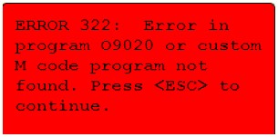 ERROR 322: Fehler in Programm O9020 oder Custom M Code Program nicht gefunden. Drücke < ESC > für weiter |
Parameter File Version Used to track software during updates.
*****Inch Precision***** Used for displaying inch values other than axis positions.
Cartesian Leading
Cartesian Trailing
Angular Leading
Angular Trailing
Spindle Leading
Spindle Trailing
Feedrate Leading
Feedrate Trailing
*****Metric Precision***** Used for displaying metric values other than axis positions.
Cartesian Leading
Cartesian Trailing
Angular Leading
Angular Trailing
Spindle Leading
Spindle Trailing
Feedrate Leading
Feedrate Trailing
Notes on Parameters
Note 1: On any given parameter screen, parameter values are written when Esc- ing to
the main menu. After editing parameters, whether they be Power parameters or any other
parameters, remember to Escape to the main menu before powering down the control.
Note 2: For new power parameters to take effect, the machine must be powered down then
up again. Power parameters are so named because they are read only on power-up.
When the G or M code is executed the 090## program (in the ram folder) associated will
be called. All custom codes are checked for syntax errors prior to running any program
(or MDI command). If an error is found (or the 090## file is not found) a message is shown:
Machine Setup AXIS Parameters
| Axis Address Label X 88 Y 89 Z 90 |
ASCII code for axis assignments |
| Pulses Per Unit X 25400.0 Y 25400.0 Z 25400.0 |
The number of encoder pulses (actual or simulated) per unit of travel; generally depends on drive type and drive setup. |
| Encoder Multiplier X 1 Y 1 Z 1 |
When multiplier is 0, pulses after quadrature are divided by 4; When multiplier is 1, divided by 2; when multiplier is 2, divided by 4. It works backwards. Higher multiplier means fewer encoder pulses. |
| Home Position X 00.0000 Y 00.0000 Z 00.0000 |
The dimension assigned to the machine zero or home position. Sometimes used in rotary axis that do not home at zero. |
| Home Direction X 0 Y 0 Z 0 |
Defines the direction an axis moves when a home is commanded. CW = 0 CCW = 1 |
| Velocity Toward Home X 60.0000 Y 60.0000 Z 60.0000 |
Sets the velocity at which an axis seeks the home limit switch. |
| Velocity Away From Home X 12.0000 Y 12.0000 Z 12.0000 |
Sets the velocity at which an axis moves off the home switch |
| Velocity Toward Marker X 02.0000 Y 02.0000 Z 02.0000 |
Sets the velocity at which an axis searches for the encoder marker pulse. |
| Home Sequence X 2 Y 2 Z 1 |
These numbers determine the order in which the axes seek home: #1 first, #2 next, etc. Axes with the same number home together. 0 will cause that axis not to seek home. |
| Home Switch=0 Marker=1 X 0 Y 0 Z 0 |
A zero setting commands the normal homing algorithm, where the axis finds the switch before finding the marker; with a 1 setting, the axis simply finds the closest marker. |
| Positive Limit X 00.1000 Y 00.1000 Z 00.1000 |
Dimension from machine zero where the positive software limit occurs . |
| Negative Limit X -40.000 Y -20.000 Z -26.000 |
Dimension from machine zero where the negative software limit occurs. |
| Maximum Feed X 300.000 Y 300.000 Z 300.000 |
Sets the maximum G01, G02, G03 feedrate in inches per minute or mm per minute. High limit is the value for rapid velocity. |
| Dry Run Feed X 75.0000 Y 75.0000 Z 75.0000 |
Sets the dry run feedrate in inches per minute or mm per minute |
| Rapid Velocity X 1000.000 Y 1000.000 Z 1000.000 |
Set the maximum G00 feedrate in inches per minute or mm per minute |
| Max Acceleration X 150.000 Y 150.000 Z 150.000 |
The rate velocity increases or decreases in in⁄sec^2; depends on servo drive⁄motor sizing relative to the axis load being driven. 9000 CNC motion control algorithm manages acceleration to prevent harsh forces. |
| Jerk Limit X 2000.00 Y 2000.00 Z 2000.00 |
The rate acceleration increases or decreases in in⁄sec^3; a good all purpose value is 2000. High jerk values reduce cycle time; machine motion is more violent. Lower values extend cycle time, machine motion is smoother. These default values are used in the absence of G187, G188, G189 calls. |
| G187 Jerk Limit X 6000.00 Y 6000.00 Z 6000.00 |
Jerk values for roughing, used when G187 is commanded in a program. Cycle time is reduced. Machine motion is more violent. |
| G188 Jerk Limit X 4000.00 Y 4000.00 Z 4000.00 |
Jerk values for semi-finishing, used when G188 is commanded in a program. |
| G189 Jerk Limit X 2000.00 Y 2000.00 Z 2000.00 |
Jerk values for finishing, used when G189 is commanded in a program. Cycle time is greater. Machine motion is smoother. |
| Jog Velocity X 200.0000 Y 200.0000 Z 200.0000 |
Velocity in IPM or MMPM |
| Jog Key Direction X 0 Y 0 Z 0 |
Sets whether the Jog is related to moving the table or moving the tool. A “1” reverses direction. |
| In Position X 00.0050 Y 00.0050 Z 00.0050 |
After any rapid move, the machine will wait until the axis is within this distance from the target destination before starting the next block. |
| G00 Unidirectional X 00.0000 Y 00.0000 Z 00.0000 |
Sets the distance in inches or mm which an axis will go past the destination point in one direction before reversing direction so that the machine will always position from the same direction. Active only in G00 mode.  |
| G60 Unidirectional X 00.0000 Y 00.0000 Z 00.0000 |
Same as G00 unidirectional except only active in a G60 block |
| Backlash X 00.0002 Y 00.0002 Z 00.0000 |
Backlash compensation in inches or mm. The control compensates for lost motion whenever an axis reversal takes place. Active in all modes. Set when the machine is calibrated. |
| Excess Error X 00.4000 Y 00.4000 Z 00.4000 |
Sets the max distance in inches or mm the machine lags desired position. The CNC e-stops the system if excess error is exceeded. An important safety parameter. A zero value turns off excess error checking. |
| Rotary=0 Linear=1 X 1 Y 1 Z 1 |
Sets whether the cnc treats an axis as rotary or linear. In rotary, feedrate is interpreted as degrees per minute rather than distance per minute. There is no conversion between inch and metric for a rotary axis. |
| Rotary Rollover Off = 0 On = 1 |
If Rotary Rollover = 1, then all rotary axis positions are modulus 360, i.e., between 0 and 360. An absolute move command goes the shorter way to a target position and hence never goes more than 180 degrees. An incremental move command goes in the direction specified and hence may go more than 180 degrees. If Rotary Rollover = 0, then rotary axis position may range from -1,000,000 degrees to +1,000,000 degrees. |
| Handwheel Normal=0 Invert=1 X 0 Y 0 Z 0 |
A “1” will reverse the direction of the handwheel. |
| Inch Leading X 2 Y 2 Z 2 |
Sets the number of characters to the left of the decimal point for the inch system, for the specified axis only |
| Inch Trailing X 4 Y 4 Z 4 |
Sets the number of characters to the right of the decimal point for the inch system, for the specified axis only |
| Metric Leading X 4 Y 4 Z 4 |
Same as Inch Leading except for the metric case |
| Metric Trailing X 3 Y 3 Z 3 |
Same as Inch Trailing except for the metric case |
| Max Handwheel Error X 00.3000 Y 00.3000 Z 00.3000 |
When handwheeling, if following error reaches this value, pulses from the handwheel are ignored. Error is specified in inches or mm. Prevents excess error e-stop if operator gives a rapid spin to the Handwheel. Max Handwheel Error should be set to Excess Error - .100. |
| Proportional Gain X 03.2000 Y 03.2000 Z 03.2000 |
Scaling factor between following error and velocity command signal to the drive. Reasonable values are between 2 and 8. |
| Velocity Gain X 20.0000 Y 20.0000 Z 20.0000 |
Scaling factor between desired velocity and velocity command signal to the drive. Reasonable values are between 10 and 70, these default values used in the absence of G187, G188, or G189. (see below) |
| Handwheel Gain X 01.0000 Y 01.0000 Z 01.0000 |
Same as proportional gain. Smaller values are used to soften handwheel motion. Reasonable values are between 1 and 4. |
| G187 Velocity Gain X 10.0000 Y 10.0000 Z 10.0000 |
Scaling factor between desired velocity and velocity command signal to the drive when in G187 mode. Reasonable values are between 10 and 70. |
| G188 Velocity Gain X 15.0000 Y 15.0000 Z 15.0000 |
Scaling factor between desired velocity and velocity command signal to the drive when in G188 mode. Reasonable values are between 10 and 70. |
| G189 Velocity Gain X 20.0000 Y 20.0000 Z 20.0000 |
Scaling factor between desired velocity and velocity command signal to the drive when in G189 mode. Reasonable values are between 10 and 70. |
Machine Setup MISC Parameters
****Basic Machine Info****
Machine Type: Type in VM3018, etc.
Machine Version: The current model
Mechanical Version: The current mechanical version
Electrical version: The current electrical version
Machine serial number: The machine serial number
Slow Rapid Percent: Sets the percent of rapid when the leftmost of the three molded front
panel Rapid keys is active. Generally set to 10, matching the 10% embossed on the key.
Check Spindle Up to Speed:
“Off” – The control never waits for a spindle up to speed signal.
“On (M3⁄M4)” - The control will wait for up-to-speed signal from the spindle controller after
an M3 or M4 command.
“From Rapids to Feeds”:
The control will wait for an up-to-speed signal from the spindle controller before continuing
to a G1, G2, or G3 block from a G0 block.
Up to Speed Input #: Specifies the input for the up to speed signal.
Watch Spindle Up to Speed: If set to YES, then the control will watch the up to speed signal.
The control will not watch for a specified time after the spindle starts or after the Spindle override
is moved. The time is based on the MISC parameters Spindle Ramp Time 1 (if it’s in gear 1)
or spindle Ramp Time 2 (if it’s in any other gear). If the up to speed signal is not seen the control
will feedhold the machine and display the message: “The spindle up to speed signal was lost
while the spindle was running. The spindle may have stalled.” Please note that the up to speed
only looks at motor speed when the drive is running in Flux Vector Mode. This means that an
F7, MC5 or G5 running open loop vector will not work in the manner described above as
the up to speed is looking at the frequency out of the drive, not the actual motor speed.
Spindle Encoder PPU1:
Pulses per rev of spindle, used for hard tapping option and displaying the RPM in gear 1
Spindle encoder PPU2:
Pulses per rev of spindle, used for hard tapping option and displaying the RPM in any
gear other than 1.
Handwheel Encoder PPU: Pulses per rev of the handwheel, usually 400.
Spindle Range 1 Max spindle speed for gear 1
Spindle Range 2 Max spindle speed for gear 2
Spindle Range 8 Max spindle speed for gear 8
Spindle Range What gear the spindle is in
Maximum Spindle Speed: This will clamp the overall spindle speed. An important parameter
for protecting the spindle itself. Max rated rpm for the spindle is usually stamped on it.
Spindle Ramp Time 1 (sec): The tapping deceleration point is adjusted based on spindle RPM,
pitch, and spindle ramp time so as not to overshoot the programmed depth. It is the time in
seconds to slow the spindle to 0 RPM’s from full RPM’s in gear 1.
Spindle Ramp Time 2 (sec): Time in seconds to decelerate the spindle to 0 RPM’s from
full RPM’s in any gear other than 1.
Spindle Ramp Time Top: In hard tapping, how long from spindle at full scale in one direction to
full scale in the other direction, the reversal the spindle must execute after the tap exits the hole.
Setting the parameter too high makes for excessive delay; setting it too low causes the Z axis
to thump.
Tap Up Double: When set to Yes, in hard tapping operations, the tap is withdrawn from
a hole at twice the spindle RPM (and hence twice the feedrate) compared to going in.
2 Gear Spindle Motor: Yes for spindle drives with 2 gear spindle motors. The spindle
does not need to stop to shift.
Electronic Spindle Gear: Yes enables the shifting of electronic geared spindle drives.
Spindle Gear Box: Yes for machines with a mechanical spindle gear box.
Hard Tap Fudge Factor: Used to adjust the depth of rigid tapping cycle. Higher numbers
decrease the amount of overshoot at the bottom of the hole. Default value = 70.0.
Feed Back on Quill Scale: Yes enables the glass scale for Z axis quill options.
Quill Epsilon: If the value is zero no error checking is done for quill movement. If the
value is none zero, quill motion is monitored while a program is running. If the quill moves,
the control goes into block mode and an error “Quill movement detected. Reposition the Quill
to its original position -00.2800 in. Current pos: -00.1600” will be displayed.
The program will not continue until the quill is returned to its original position. The position
of the quill at the start of a program (or during tool changes) is saved and used to compensate
Z positions during the program.
Note: Quill movement is allowed while waiting for Tool Reset.
Quill Scale Encoder: The encoder to use for the glass scale for Z axis quill options.
Quill Scale PPU: The pulses per inch for the quill scale encoder.
Back Gear Reverse: Yes only for small semi-manual mills where back gear reverses
spindle rotation.
AC Brushless Axis Motors: Generally Yes.
Check Air Pressure: If the parameter is set to Yes and air pressure is low, the machine
e-stops and the control puts up a low air pressure alarm red message box.
FeedHold Input: Input # for the feedhold signal, which is usually the door open switch.
Check Tool Door Open: Used on old 20 pocket platter style tool changes.
European Code: Yes or No. See notes on European Code at the end of this section.
Chiller Fault Input #: The input # for chiller faults. Causes an error #1395 Chiller Fault
message if the input is read.
Cool-Down Time (min): Used on spindle air-purge systems.
Lube Cycle Time (min): Used on spindle air-oil lubricating systems.
Grease Cycle Time (hour): Time in hours between grease pump cycles
Grease ESTOP Time (sec): Time in seconds the control will E-stop if pump stop input
(#60, J2-24) does not change to a “1” within the specified amount of time once the grease
pump cycle has started.
Way Lube On Time (sec): Time in seconds for the waylube pump to run in a cycle
Way Lube Off Time (min): Time in minutes for the waylube pump to pause in a cycle
Recycle Pump Time (sec): Used on coolant-through-spindle (CTS) systems.
Coolant Thru Spindle Type: Yes if machine has CTS.
Auto Door Open: Enables the door open option.
Auxl Button Function: If set to 1, Aux1 button toggles user M-Code M65⁄M75 which toggles
output 30 (Z-out 6). If set to 2, Aux1 button toggles auto door. Default is 0, not enabled.
Max Feed w⁄Door Open: See notes on European code (page 10-33) later in this section.
Spindle Probe: Enables the handwheel probing cycles
Probe Input #: Input to use for probe commands.
Cranking Minutes⁄Rev How many minutes of normal program execution time correspond
to one turn of the handwheel. Multiplying an IPM feed time, this factor results in an IPR feed
(inches per turn of the handwheel). This parameter should be approximately 0.0010 for our
current systems.
Cranking Factor: Multiplier for each handwheel click is approximately 100 for our current
systems. Cranking⁄Factor⁄Cranking MinsPerRev is proportional to the max feedrate allowed
while hand-cranking.
Cranking Max IPM: This limits the feedrate while hand-cranking to get reasonable response at
slow programmed feedrates. Adjusting the other parameters can give excess errors on rapids.
This parameter should be approximately 100 for our current systems.
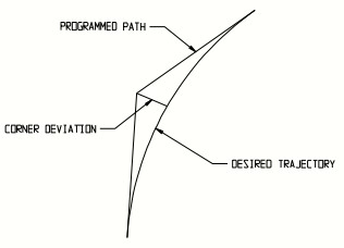
Max Corner Deviation: This number sets a default value for the maximum deviation allowed
on a corner, in the absence of a G187, G188 or G189 command. A value of .002 means
the control generates a desired path within. .002” of the programmed path.
G187 Max Corner Deviation: .010 is a good value for roughing, allowing reduced cycle time
when accuracy is less important.
G188 Max Corner Deviation: .005 for semi-finishing.
G189 Max Corner Deviation: .002 for finishing.
Always stop if corner is: There are two possible values, 90 degrees and 60 degrees.
90 degrees works well.
Min Block Time (sec): A legacy parameter. Now generally set to zero.
Tri-Color Cycle Light: Yes if it has the 3 color (Red, Yellow and Green) Cycle Light.
End-of-Cycle Output #: The end of cycle light output #. Zero if it doesn’t have an end of cycle light.
Cylinder Parked Axis: See Section 6 on Cylindrical mapping (G107) Normally set to 2 (for the Y axis).
Cylinder Rotary Axis: Normally set to 4 (for the A axis).
Data Log Input #: Future use, M7
Data Log Path: Future use, M7
Data Log Network Folder Future use, M7
Allow Modal Restart: Enables the ability to start programs from a specific block in the block.
The block is selected using the program editor. It also allows the ability to pick up on modes,
before the selected block, such as federates, spindle commands, tool#s, cutter comp, etc.
Allow Away Offsets: Enables the Mill away feature. If selected the operator can halt a program,
move the tool and resume the program using offsets related to the distance moved.
****Software Options****
Look Ahead Blocks: The maximum number of blocks the control is allowed to look ahead.
The 9000 Series CNC uses an adaptive lookahead algorithm. It looks no further ahead than
it has to. 99.99% of applications require nowhere near the max number of Look Ahead Blocks.
Dependent on processor capacity. Setting is 80 on Series 9000 CNC’s in early 2016.
Look Scope Blocks: Generally set to zero.
Transition Radius: A first cousin to the earlier parameter Max Corner Deviation, defining how
closely the desired path follows the programmed path at corners. A lower value creates
a desired path closer to the programmed path. A higher value permits smoothing the corner,
reducing cycle time. This default value is used if there is no G187, G188 or G189 command
in the program. Usually .020.
G187 Transition Radius: Transition radius for roughing. A higher value permits a reduced
cycle time. Usually .050.
G188 Transition Radius: Transition radius for semi-finishing. Usually .035.
G189 Transition Radius Transition radius for finishing. Usually .020.
Small Move Multiplier: Allows higher speeds in tiny line segments, producing faster and
smoother overall performance. A good value is 8.
Max solid graph file size: The high limit for a solid model graphics file. Dependent on
processor capacity and graphics chipset. Usually 30,000.
Graph look-ahead: Specifies the number of lines and arcs that are graphically displayed
ahead of the tool. The default is 15, the allowable range is between 1-200.
G18 is XZ plane: (X is the primary axis) or ZX plane (Z is the primary axis)
G93 is: 1⁄min or 1⁄sec for inverse feedrates
Special Flags: Normally set to 0
Bit 2 (#2) will shut off trig help.
Bit 3 (#4) will shut off cutter compensation.
Note: Trig Help is cnc background functionality that finds arc endpoints and tangents in
conversational programs. The output from some CAD⁄CAM systems plays poorly with
Trig Help. If this interference occurs, usually shown by a huge arc in the toolpath when
it should be a small arc, machine performance is corrected by turning Trig Help off.
Setting Misc parameter Special Flags to 2 (turning off Trig Help) does not help the situation,
because the setting does not persist. There are certain Prog-Run defaults invoked by the CNC
when any program is run. One of them is to enable Trig Help.
A workaround for this circumstance is to insert a line “PB81 = 2” near the top of any CAD⁄CAM
text program. A CAD⁄CAM post processor can usually be edited to add this line automatically.
Another workaround is to set PB208 = 0 in MDI. If PB208 equals 0, then Trig Help is not
turned on as a Prog-Run default and thus the setting in Misc parameters Special Flags does
persist. The value in PB208 persists through power cycles, i.e. when PB208 has been set to
zero and Special Flags = 2, then Trig Help is turned off and remains off.
G5#-Z in Handwheel: If set to Yes, G5#-Z will be on the handwheel screen.
The option is for machines with a tool setter (or those that touch tools off on the table).
Tool Setting: If set to Current Tool when setting tool lengths the control assumes that
the active tool # is the tool length that is being set. If set to Any Tool the control will prompt
the operator for the tool #. Tool Setting, Using Work Offsets If set to Yes, the work offsets
are used when setting the tool length. The option is for those that touch tools off on the table.
90 degree Cutter Comp: If set to Yes, the tool is positioned at 90 degrees when cutter comp
is activated (with G41 or G42) or deactivated (with G40).
SingleBlock thru CannedCycles and TC’s:
If set to Yes, (and in single block) tool changes, drill cycles and canned cycles are executed
with 1 cycle start.
If set to No each block of the tool changes, drill cycles or canned cycle requires a cycle start.
2 nd On Pocket Prox Input #:
Set to the input# for the 2 nd on pocket switch on tool change carousels.
Set to zero if does not have a 2 nd on pocket switch.
CPU Warning Temperature: If set to a non-zero value and the value is exceeded a
message WARNING: CPU is dangerously warm.
To avoid abrupt shutdown, shutdown the machine as soon as possible. Press<ESC>
to clear this message.
****CAD Parameters****
CAD Type is CAD file type to import in DXF or IGS programming.
CAD Epsilon Tolerance for geometry intersections of imported CAD files.
****Post M codes table****
Post M code #0 M codes listed here will be executed after all other
Post M code #1 operations within the block.
Post M code #2
Post M code #3
Post M code #4
Post M code #5
Post M code #6
Post M code #7
Post M code #8
Post M code #9
****Spindle Power Monitoring****
Spindle Power Raw Value read from ADC, 0 to 255
Spindle Power Scale Multiplier to obtain Spindle Power Value
Spindle Power Value (Amps) Calculated from the spindle power raw and scale
****Thermal Compensation****
SENSOR #1
#1 Comp Axis The number of the axis that is being compensated.
#1 Position of Sensor The position (machine relative) the sensor is mounted.
#1 Voltage Reference Voltage above this value indicates "growth", values below indicate
"shrinkage".
#1 Position Reference The position (machine relative) corresponding to the fixed end of the
ballscrew.
#1 Lower Backlash (inch) The expected amount of voltage change when direction is
reversed. This value is due to coupling between the ballscrew and the motor.
This value is set by the calibration cycle.
#1 Inches⁄Volt For sensors that measure position displacement, the displacement per volt.
#1 Degrees⁄Volt For sensors that measure temperature, the temperature change per volt.
#1 Inverse Growth⁄Degree For temperature sensors used on a ballscrew, the percentage growth
of the ballscrew per degree (or rather the inverse). If using Centigrade,this parameter will be
about 1⁄.000011 for a steel ballscrew.
#1 Inches⁄Degree For temperature sensors mounted on the head indicating spindle displacement,
the displacement of the spindle per degree.
#1 Adjust Position A (in)
#1 Adjust Voltage A
#1 Adjust Position B (in)
#1 Adjust Voltage B
The above four parameters allow an adjustment to the voltage based on the current position
of the axis. The amount of correction is calculated by linearly interpolating the values at the
two given points. These values are set by the calibration cycle.
(These thermal comp fields are repeated for seven axes)
ENCODER COMPENSATION
Comp Axis The number of the axis that is being compensated.
Encoder Axis The encoder number the comp is based off of.
Encoder PPU The Pulses Per Unit of the comp encoder.
Comp Factor The amount of comp applied per change in position of the encoder axis.
European Code Parameter and Operation Descriptions
European Code: Limits axis and spindle motion as described below
Feedhold Input: The input for signaling feedhold to the CNC. Depending on machine safety
requirements, the door switch or light curtain signal usually goes to the feedhold input.
Setup Button: The feedhold override button, a hold-to-run switch in some European code
scenarios.
When European Code is set to Yes, the CNC software limits machine behavior to comply with
European Union safety regulations. Below is a description of how the software operates.
If the door open switch is wired to the feedhold input and European Code = No: When
the door opens, it shuts the spindle off and feedholds the machine. When the door is open,
the spindle will not start. When the door is open, the machine will not do an MDI move, will not jog,
and will not do a move in run mode; however, it will handwheel.
The machine will do I⁄O related functions other than turning on the spindle (i.e. arm-in, drawbar, etc.)
If the machine is tapping and the doors open, the machine will finish the tap, feedhold, and stop the
spindle.
If the doors are opened while the machine is running:
1. The spindle will shut off.
2. The axis will stop moving.
3. The feedhold light will come on.
4. The spindle will not restart.
To continue operation:
1. Close the doors (Cycle Start will flash).
2. Push the CW button on the front panel (the spindle will restart).
3. Push the Cycle Start Button on the front panel (Cycle Start will stop flashing and the
Feedhold light will go out).
If the machine is not running and the spindle is not running, opening the doors should have no
effect on the machine. However, the Feedhold light will come on.
If the door open switch is wired to the feedhold input and European Code = Yes When the door
opens, which is allowed by pressing the door open button, the spindle shuts off as well as
feedholds the machine. When the door is open, the spindle will not start. When the door is open,
the machine will not do an MDI command; it will not jog nor will it start running a program. It will not
handwheel. If the machine is tapping and the doors open, the machine will finish the tap and then
feedhold and stop the spindle.
If the door is open, the machine will allow the tool changer to index only one position at a time using
the tool changer utility or the tool setting utility.
If the door is open and Setup is held in, the machine will jog up to 60 ipm.
If the door is open and Setup is held in, the machine will handwheel up to the 50% rate on the
feedrate override switch, which is .1mm per click of the handwheel. (It is difficult to generate
speeds greater than 1000 mmpm in this mode). Modifying the distance per click of the handwheel
also requires a password available only to the machine builder.
If the doors are opened while the machine is running:
1. The spindle will shut off.
2. The axis will stop moving.
3. The feed-hold light will come on.
4. The spindle will not restart.
If Setup is pressed, the machine will move at the clamped feedrate while the button is held in.
To continue operation:
1. Close the doors (the Cycle Start Button will flash).
2. Push the CW button on the front panel (the spindle will restart).
3. Push the Cycle Start Button on the front panel (the Cycle Start Button will stop flashing and
the feedhold light will go out).